


Calibration of RTD:
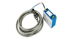
RTD as known Resistance Temperature detector that use for temperature sensing & Measuring purpose. RTD is a highly sensitive Temperature detector. That most commonly use on emergency shutdown system ESD. PT100 is common and most used in any industry. RTD have some other type like PT50 PT100 PT1000.

A RTD or Resistance Temperature Detector is a passive circuit element whose resistance increases with increasing temperature in a predictable manner. RTD element is constructed of a small coil of platinum, copper, or nickel wire, more recently, RTDs are also being constructed using a thin-film of platinum or nickel-iron metal deposited on a ceramic substrate and then laser-trimmed to a desired reference resistance. The advantage offered by this construction is that the thin-film elements can achieve a higher resistance with less metal, and over smaller areas.


0 Comments